AMD FidelityFX™ Variable Shading
AMD FidelityFX Variable Shading 将可变速率着色引入您的游戏。
In this part of the blog post, we’re going to discuss some best practices for getting the best performance out of mesh nodes. We’re also going to look at some tips and tricks, that might come in handy when working with mesh nodes.
First and foremost, mesh nodes are essentially just mesh shaders inside of a work graph. Thus, when it comes to writing the mesh shader part of your mesh nodes, all the best practices for mesh shaders that we outlined in our mesh shader blog post series also apply here.
As mentioned in the introduction, the addition of mesh nodes to work graphs essentially turn the work graph into an amplification shader on steroids. This, however, also means that the same recommendations for launching mesh shader workloads from amplification shaders apply to work graphs. In particular, every mesh shader dispatch, i.e., every record sent to a mesh node, should contain enough mesh shader work (mesh shader thread groups) to hide the latency and overhead associated with launching the mesh shader.
In the following, we’re going to discuss how you can (re-)structure your graph to launch larger mesh node dispatches, and - if such graph structures do not fit your use-case - how coalescing nodes can be used to dynamically bundle mesh node work into larger dispatches.
Note: Performance of launching many small dispatches of the same mesh node will likely improve during the preview. We however still recommend you - if possible - to structure your graph such that larger mesh node dispatches are launched at a time.
With work graphs and mesh nodes, a common scenario for launching mesh node work might be to process one item per thread in a larger broadcasting node. Such an item might be a single meshlet, for which the thread performs visibility checks for culling, and then launches a mesh node to draw it.
The following example shows how such a one-thread-per-meshlet node might be implemented.
struct DrawMeshletRecord {    // data to draw one meshlet    ...};
[Shader("node")][NodeLaunch("broadcasting")][NodeMaxDispatchGrid(1024, 1, 1)][NumThreads(64, 1, 1)]void ProcessMeshlets(    uint dispatchThreadId : SV_DispatchThreadId,
    DispatchNodeInputRecord<ProcessMeshletsRecord> input,
    // One output per thread to draw a meshlet with a mesh node    [MaxRecords(64)]    NodeOutput<DrawMeshletRecord> DrawMeshlet) {    ...
    // Allocate one output if meshlet is visible    ThreadNodeOutputRecords<DrawMeshletRecord> outputRecord =        DrawMeshlet.GetThreadNodeOutputRecords(isMeshletVisible);
    if (isMeshletVisible) {        outputRecord.Get() = ...;    }
    outputRecord.OutputComplete();}
Here, each thread group can output up to 64 records, one per thread, to the DrawMeshlet mesh node. Each thread of the ProcessMeshlets node processes one meshlet and uses GetThreadNodeOutputRecords to allocate one output record, if the meshlet is visible.
In this case, the DrawMeshlet node would specify a [NodeDispatchGrid(1, 1, 1)] attribute, meaning only one thread group is launched per incoming record.
This may result in a significant performance overhead and low occupancy for the mesh node. To mitigate this, we can restructure the ProcessMeshlets node to instead output a single record, which contains data for multiple meshlet to be drawn.
struct DrawMeshletRecord {    // data to draw one meshlet    ...};
struct DrawMeshletBundleRecord {    // data to draw up to 64 meshlets    DrawMeshletRecord meshlets[64];    // number of meshlet to draw, i.e. number of mesh shader thread groups to launch    uint meshletCount : SV_DispatchGrid;}
[Shader("node")][NodeLaunch("broadcasting")][NodeMaxDispatchGrid(1024, 1, 1)][NumThreads(64, 1, 1)]void ProcessMeshlets(    uint dispatchThreadId : SV_DispatchThreadId,
    DispatchNodeInputRecord<ProcessMeshletsRecord> input,
    // One output per thread group to draw up to 64 meshlets with a mesh node    [MaxRecords(1)]    NodeOutput<DrawMeshletBundleRecord> DrawMeshletBundle) {    ...
    const uint totalMeshletCount = WaveActiveCountBits(isMeshletVisible);
    // Allocate one output for entire thread group    GroupNodeOutputRecords<DrawMeshletRecord> outputRecord =        DrawMeshletBundle.GetGroupNodeOutputRecords(totalMeshletCount > 1);
    outputRecord.Get().meshletCount = totalMeshletCount;
    if (isMeshletVisible) {        outputRecord.Get().meshlets[WavePrefixCountBits(isMeshletVisible)] = ...;    }
    outputRecord.OutputComplete();}
Now, we define a larger DrawMeshletBundleRecord to combine the data of all of the 64 threads of the thread group. We can now use GetGroupNodeOutputRecords to allocate a single record, which is shared across the entire thread group. Every thread that wants to draw a meshlet can then simply write its data to the meshlets array in this shared record. For simplicity, we’re assuming that this node will run in wave64 mode and thus we can use WaveActiveCountBits and WavePrefixCountBits to synchronize both the number of meshlets and the access to the meshlets array. If you’re using larger thread groups, or you’re running on hardware that does not support wave64, you can use a groupshared counter variable in combination with an atomic InterlockedAdd to achieve the same result. You can find example code for this in the mesh node sample.
To accommodate this bundled record, we also need to update the mesh node to a dynamic dispatch grid with up to 64 thread groups.
[Shader("node")][NodeLaunch("mesh")]// we're now using a dynamic dispatch grid with up 64 thread groups[NodeMaxDispatchGrid(64, 1, 1)][NumThreads(128, 1, 1)][OutputTopology("triangle")]void DrawMeshletBundle( uint gid : SV_GroupId, uint gtid : SV_GroupThreadId, DispatchNodeInputRecord<DrawMeshletBundleRecord> inputRecord, ...){ // load meshlet record for this thread group from DrawMeshletBundleRecord const DrawMeshletRecord record = inputRecord.Get().meshlets[gid];}Further, we need to change the access to the input record, as every thread group now needs to access a single element in the data array, instead of the entire input record.
Note: due to an issue in the DirectX® Shader Compiler, we recommend accessing array in a node input record with
const Element element = inputRecord.Get().array[index];.
Accessing arrays from a local copy of the input record, e.g., with
const Record record = inputRecord.Get();
const Element element = record.array[index];
may lead to unexpected loads to the entire array, which can affect performance.
With these changes in place, we’ve decreased the number of mesh node dispatches, as we’re only outputting a single record for each thread group of our producer node. At the same time, each of these records is launching up to 64 mesh shader thread groups and thus helps to hide the mesh shader launch overhead.
That said, we’ve also increased the size of a single record, thus potentially wasting memory if less than 64 meshlets are drawn with a single record. We’re using 64 meshlets per record as an example here, as for most workloads, this should be enough to achieve good mesh shader occupancy. We do, however, recommend you to check the actual sizes of the mesh node dispatches, either through manual instrumentation or with the help of the Radeon™ GPU Profiler and adjust this number if needed. Launching mesh nodes is similar to calling DispatchMesh in an amplification shader, and we’ve already covered how you can use the Radeon™ GPU Profiler to profile such workloads here.
If your workload cannot be restructured to output such bundled mesh node records as described above, or does not consistently fill these bundles enough to saturate the GPU with mesh shader work, you can also use coalescing nodes to increase mesh node dispatch sizes.
A coalescing node can receive multiple input records per one thread group and can process them together. This can have a wide range of different applications, but in our case we can use it to combine multiple mesh node records into a single, combined record.
In this example, we will again focus on rendering meshlets, but this can also be adapted to different scenarios.
struct DrawMeshletRecord {    // data to draw one meshlet    ...};
struct DrawMeshletBundleRecord {    // data to draw up to 64 meshlets    DrawMeshletRecord meshlets[64];    // number of meshlet to draw, i.e., number of mesh shader thread groups to launch    uint meshletCount : SV_DispatchGrid;}
[Shader("node")][NodeLaunch("coalescing")][NumThreads(64, 1, 1)]void DrawMeshlet(    uint threadIndex : SV_GroupIndex,
    // receive up to 64 "draw-calls" for different meshlets    [MaxRecords(64)]    GroupNodeInputRecords<DrawMeshletRecord> input,
    // one coalesced bundle output with up to 64 meshlets    [MaxRecords(1)]    NodeOutput<DrawMeshletBundleRecord> DrawMeshletBundle){    GroupNodeOutputRecords<DrawMeshletBundleRecord> outputRecord =        DrawMeshletBundle.GetGroupNodeOutputRecords(1);
    outputRecord.Get().meshletCount = input.Count();
    if (threadIndex < input.Count()) {        outputRecord.Get().meshlets[threadIndex] = input.Get(threadIndex);    }
    outputRecord.OutputComplete();}
In this case, we’re again using 64 meshlets per mesh node record as an example, and we again recommend to use profiling and tweak this number accordingly.
This example focused on combining, or coalescing mesh node records for single meshlets, but this concept can also be applied to other use-cases, e.g., entire meshes. The procedural generation demo that we’ve showed at GDC 2024 uses a coalescing node to combine draw calls (i.e., mesh node records) for the same mesh into instanced draw calls. This way, records were coalesced to just mesh node records. You can learn more about this and the procedural effects of the GDC 2024 demo in our upcoming paper, which will be published at HPG 2024.
In addition to combining multiple records into larger bundles, coalescing nodes can also perform additional work on those records. For example the MeshNodeSample uses coalescing nodes to procedurally generate up to 32 trees in a single thread group. Each tree is defined as a set of one or more splines and up to 32 splines are combined into a single mesh node record.
To summarize, for optimal performance, mesh nodes should be launched in larger dispatches. Such dispatches can be achieved by restructuring certain aspects of the graph, or by using explicit coalescing nodes to combine multiple smaller dispatches.
Mesh nodes introduce a new way of launching mesh shader work directly from the GPU. Unlike regular amplification shader pipelines, which could already launch mesh shader work, but in a more limited fashion, mesh nodes also allow for full pipeline state object (PSO) switching.
Graphics PSO switching, whether it’s from the CPU through a command list or from the GPU in a work graph can be a quite expensive operation. With work graphs, all the different graphics pipeline states, and thereby all the potential transitions are known upfront. From this, the driver can determine a common graphics pipeline state across all the different mesh node PSOs. Depending on the variance in state across your mesh nodes, this can greatly reduce the costs of PSO switching.
So, what does this mean for your application? As a general rule of thumb, try to keep the overall state variance down to simplify PSO switching. The cost of a PSO change is proportional to the number of state parameters that cannot be combined into the common graphics state.
Simple state parameter changes, like the mesh or pixel shader can be done fairly quickly, while other like changing the entire blend state might be more costly. If you require many different mesh nodes with vastly differing graphics pipeline states, try to saturate the virtual queues for each of these mesh nodes. In other words, if you need to perform a costly state transition, try to launch enough work to hide that latency.
Now, that we’ve seen some guidelines on optimizing performance of mesh nodes, let’s focus on some of the fun things you can do with them. We’ve seen that we can have different mesh nodes with different mesh and pixel shaders and with different graphics state. So far, all of the mesh nodes in the same work graph write their pixel shader output to the same render targets. Crucially, they also share the same depth buffer, thus making things like rendering a deferred G-buffer pass and a shadow map in the same work graph difficult.
As we can only set one render target through commandList->OMSetRenderTargets(...);, we can instead use render target texture arrays to render the output of different mesh nodes to different, independent array slices in the render targets - including independent depth buffers.
To select the render target array slice to be drawn into, we use the SV_RenderTargetArrayIndex semantic. As these different array slices may also require different viewports and scissor rectangles, we can also select a viewport using the SV_ViewportArrayIndex semantic. These semantics are specified for each triangle using per-primitive attributes.
struct PrimitiveAttributes {    uint renderTargetArrayIndex : SV_RenderTargetArrayIndex;    uint viewportArrayIndex     : SV_ViewportArrayIndex;};
[Shader("node")][NodeLaunch("mesh")]...void DrawMeshletBundle(    ...    out indices uint3                  tris[MAX_PRIMITIVES],    out primitives PrimitiveAttributes prims[MAX_PRIMITIVES]){    ...
    tris[triangleIndex] = LoadTriangle(triangleIndex);    // render primitive to render target array slide 1 and viewport 1    prims[triangleIndex].renderTargetArrayIndex = 1;    prims[triangleIndex].viewportArrayIndex     = 1;}
Even though we can choose different viewports for the different render target array slices, the underlying textures can only have a single resolution for all array slices. This means the render target texture size is determined by the largest required slice. If e.g. you want to render a deferred G-buffer pass as and a shadow map pass at , you would need to allocate all render targets at , thereby potentially wasting memory.
Alternatively, if you are willing to go down a very deep rabbit hole, you can also implement perspective shadow maps, and thus have the same render resolution for shadow and G-buffer targets.
If a particular task, e.g., drawing a procedurally generated structure requires multiple different mesh shaders to be invoked, you can share a record across multiple mesh nodes and thereby invoke multiple draws at once. Input record sharing can be specified through the [NodeShareInputOf(...)] or node overrides. Note that any shared input is counted as multiple outputs towards the output limits of the producer node.
If, for example, you’re using render target arrays as described above to render a G-buffer and shadow pass in the same work graph, you can use input sharing to invoke two different mesh shaders with different pipeline states with a single record.
The SetMaximumInputRecords function and [NodeMaxInputRecordsPerGraphEntryRecord(...)] attribute were introduced with the mesh node preview and are intended to help the runtime reduce costly transitions between compute and graphics pipelines. As mentioned in the getting started section, AMD GPUs do not require these limits to be accurately set1. Your GPU vendor however may require these hints in order to execute mesh nodes efficiently, thus we’ll discuss how you can determine safe limits.
Note: Ideally, these hints will not be needed long-term and be removed by the end of the preview-phase.
For work graphs that contain mesh nodes, SetMaximumInputRecords must be called before querying the required backing memory size. SetMaximumInputRecords defines the following limits
MaxRecords: maximum number of records that will be passed to the graph, totalled across all entry nodes.MaxNodeInputs: maximum number of node inputs, i.e., maximum number of (different) nodes that will be invoked when using D3D12_DISPATCH_MODE_MULTI_NODE_CPU_INPUT as the graph dispatch mode.For application where the input is always known (e.g. the HelloMeshNodes sample), these limits can be trivially set. If the number of input records - or at least an upper limit - is not known (e.g. one record per instance in a dynamic scene), these limits can be adjusted at runtime to fit the current input. As these limits can affect the backing memory requirements, the backing memory may need to be resized or reallocated to fit the updated requirements. In this case, the backing memory also needs to be (re-)initialized by setting the D3D12_SET_WORK_GRAPH_FLAG_INITIALIZE flag in the program description. Initializing the backing memory may be a costly operation, especially for complex graphs with many nodes. Thus, we recommend to setting the SetMaximumInputRecords limits with some margin, to avoid (re-)initializing the backing memory too often.
Tip: Only re-allocate backing memory if the memory requirements actually change. AMD GPUs ignore this limit and thus the backing memory does not need to be re-allocated or re-initialized.
The [NodeMaxInputRecordsPerGraphEntryRecord(...)] attribute is only required on complex graph topologies, and meant to help the hardware when determining backing memory requirements for mesh nodes. NodeMaxInputRecordsPerGraphEntryRecord sets a limit for the maximum number of records that may arrive at a mesh node from all possible producers per entry record. For AMD GPUs this attribute is not required, and can be safely omitted.
For simple graph topologies, the runtime can infer this limit by following the graph topology from entry nodes to mesh nodes, accumulating any amplification. For complex graphs, e.g., graphs containing node recursion or broadcast nodes, such a theoretical worst-case estimate may not be representative of the actual number of mesh node records. Thus, for such graphs, NodeMaxInputRecordsPerGraphEntryRecord should be used to set more accurate limits.
In the following, we’re going to look at two examples and see how we can set these limits through either analyzing the graph logic or using instrumentation.
HelloMeshNodes
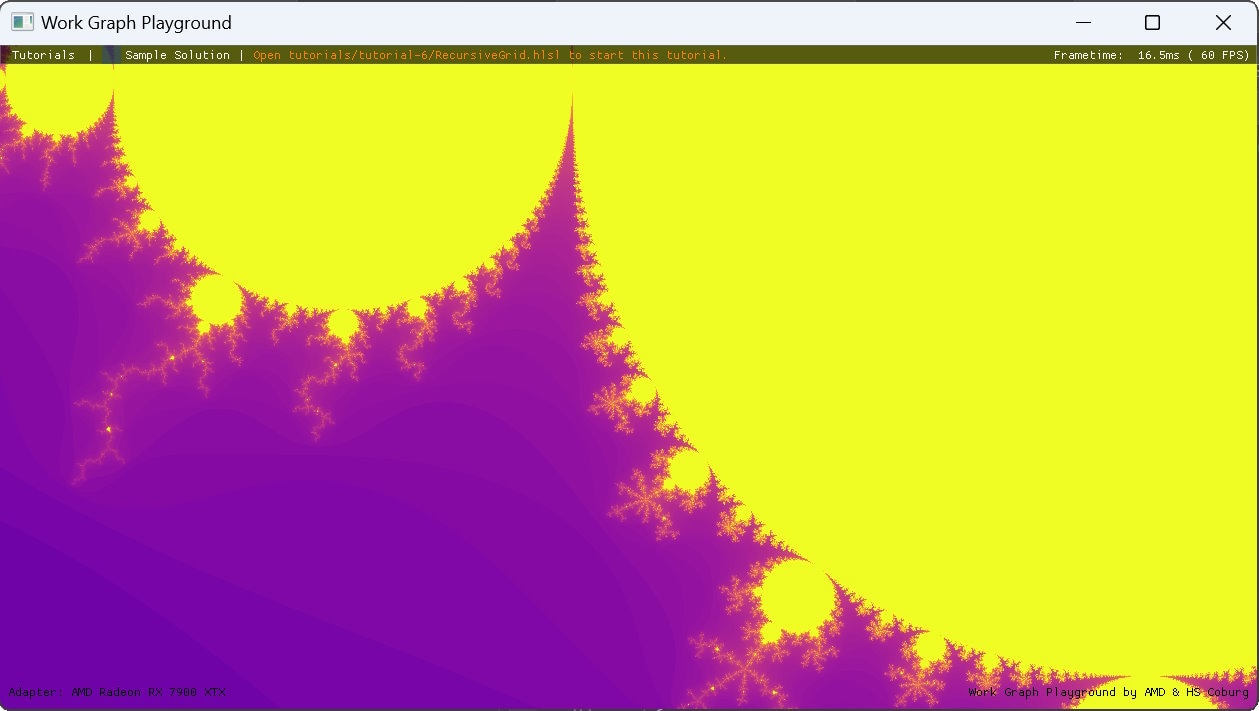
Even though this sample uses node recursion to evaluate and render the Koch snowflake fractal, its graph is rather simple. The total theoretical number of mesh node records, even with automatically inferred limits from the graph topology is thus also rather low. Thus, specifying NodeMaxInputRecordsPerGraphEntryRecord for the two mesh nodes is not strictly needed, but we’re still going to look at how the runtime determines this limit and how it compares to the actual mesh node usage.

From the graph topology, we can see that the EntryNode can directly send a single record to the TriangleMeshNode. Additionally, the entry node can send three records to the SnowflakeNode, which themselves can send one record each to the TriangleMeshNode and recurse themselves with an amplification factor of . With a maximum of three recursions, this yields a limit of
每个条目记录的 TriangleMeshNode 记录。然而,SnowflakeNode 的最后一次递归迭代只绘制线段,因此不会为 TriangleMeshNode 生成记录。因此,每个条目记录的 TriangleMeshNode 记录的实际限制是
我们已经看到,即使对于简单的图,网格节点记录的自动计算限制也可能与实际限制不同,并且需要关于图内部工作原理的附加知识才能准确确定此限制。对于逻辑简单的图,此类计算可能是可行的,但对于在每个节点上具有复杂决策的大图来说,它变得越来越不切实际。因此,接下来,我们将探讨如何通过仪器化来近似计算这些复杂图的限制。
程序化生成网格节点示例
此示例的工作图属于复杂图的范畴,按照工作图规范的定义。该示例使用多个分层网格来程序化生成世界。在这里,我们将重点介绍草皮的生成以及如何确定其限制。
分层生成网格的结构如下
World 节点是图的入口,可以启动多达 的 Chunk 线程组调度网格。Chunk 线程组最多可以启动 个 Tile 线程组。Tile 线程组最多可以启动 个 DetailedTile 线程组。DetailedTile 线程组最多可以生成2 个草皮。从入口节点到网格节点的总扩展量为
当然,不会出现如此多的草皮,因为草皮仅限于在相机视锥体和距离相机一定距离内生成。通过这种视锥体和距离剔除,草皮的实际数量永远不会超过 。由于我们总是将最多 个草皮合并到一个记录中,因此草皮的网格节点记录数也永远不会超过 。
正如我们上面所见,图拓扑结构自动生成的限制会迅速达到天文数字的高度,而实际的网格节点使用量则相当有限。在这种情况下,可以使用仪器化来近似每个网格节点的用法。由于网格节点与广播节点的行为非常相似,我们可以轻松地将任何网格节点替换为广播节点,并使用它通过原子计数器来计算传入的记录。
虽然通过仪器化确定网格节点记录的实际数量是可行的,但此限制可能无法在所有边缘情况下准确反映图。由于 NodeMaxInputRecordsPerGraphEntryRecord 在长期内将不再需要,并在预览阶段后被移除,因此可以在自动计算值导致性能和/或内存消耗问题的情况下,使用仪器化作为一种快速简便的解决方法来确定此限制。